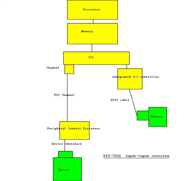
I/O Subsystems Architecture. The basis of Input and Output processing is performed in the channel processors. Channel threads are known as "execution of channel programs". The "decor" of the channels is an extension of the channel programming of the S/360 allowing for command chaining, data transfer chaining and signaling semaphores during and at the end of the execution of the channel thread. The work of the channel is coordinated with the operation of Peripheral processors that are themselves controlling the device electronics.
The level64 system implemented channels in time multiplexing the central processor hardware and channel threads were special real-time "micro-threads" of the micro-kernel. Later, on the DPS-7x0 and DPS-7000 models, the channels threads were executed in specialized I/O processors (each processor being time multiplexed between two physical channels). In some NEC high-end systems, the channel functions were split between in a very fast time-shared processor interfacing with main memory and slower processing units dealing with the physical channel. The peripheral control processors have many of functions of the device drivers and are specific minicomputers. The I/O architecture presents another degree of complexity due to the fact that several devices (operating simultaneously or not) share the same physical link (case of SCSI devices or of terminal connected through a multi-drop interface). The architecture allows mapping devices on separate logical channels hiding to the programmer the way they are actually connected. The search of resilience (and sometimes of shorter latency time) lead to connect peripherals through several channels to the CPU. The architecture is also taking care of channels crossbars and is able (if not asked to have it visible) to hide the peculiarities of the configuration. Honeywell and Bull produced several versions of PCPs, one of which –the communications front-end processor- being a standard level6 minicomputer. The other were either specially built around specific hardware data paths (then not achievable by standard minicomputers (e.g. the Billerica designed MSC mass storage controller, or built around specific architecture requirements (e.g. the URC unit record processor). Later PCP were implemented with standard microprocessor technology (usually MC-68000) and regrouped the channel functions with interface device functions. Unit Record & Service Processor The URP Unit Record Processor had a dual role of device control (Unit Record Controller) and of service processor. Its architecture was somewhat similar to the main CPU: it included a "micro-kernel" called micro-OS that handled interrupts and dispatched URC-micro-threads. Drivers micro-threads controls the URC devices (printer(s), card reader, cardpunch, paper tape reader/punch, magnetic tape cassette or 51/4 floppy disks…). Operator interface micro-thread handles at the command level interface the operator console: typewriter or the VDU (or the VDU emulator on PC –the latest avatar of the GCOS console). A specialized micro-thread is the service processor thread that in case of a central processor problem is able to take dump, to call the remote maintenance Field service and allows the remote field engineer to emulate the operator console. Actually, the service maintenance functions are executed through an interpreter of the byte code of a maintenance language that isolates the designer of maintenance procedures from the architecture of the service processor. It was not necessary to rewrite the processor maintenance code when moving from the URC to the MC68000 for the DPS-7000. Before the introduction of a Level6 front-end processor, the communications lines were also handled by the URC, through a hardware byte multiplexer and a cluster of micro-threads called together the MLA Multi-Line Adapter. At system initialization, the service processor also has the function to reset the other processors and to reload their firmware. The device threads required for initialization are partially in ROM, the service processors threads are on the floppy disk (originally on tape cassette) and the other peripheral devices are loaded from the central memory by the initialization program of the operating system (SIP). It was originally contemplated to allow the user to program the peripheral processor. In fact, only the Communications adapter and the Document Handler were given programmer control independent from the operating system. The MLA used tables defined by the programmer to specify action from specific control characters and translating data encoding. The Document Handler required the real-time control of the sorter pockets according to data contents. A specific control language was designed and a translator generated binary code to be loaded dynamically in the URC and interpreted by the URP document handler micro-thread Two distinct storage processors were designed at Billerica in 1971-1972, one for disks (Mass Storage Controller), the other for tapes (Magnetic Tape Controller). The MSC (Mass Storage Controller) was controlling the IBM format "native" disks of the Level64, but also had to attach existing H-200 drives as well as GE-100 drives. The MTC (Magnetic Tape Controller) was supporting 7-tracks and 9-tracks tapes. All existing formats 200, 556 and 800 bpi formats in NRZ and 800, 1600 bpi in PE (phase encoding) formats. When, in 1976, the complete Level 64 project was transferred in Paris, repackaged versions of MSC and MTC were produced as MSC-E and MTC-E. Those versions were motivated to save space in cabinets and to get rid of obsolete circuit parts. A new tape controller (ATP Advanced Tape Processor) designed to support the Belfort-produced GCR 6250bpi tapes (known as PENA-30) was designed by ex-CII peripheral engineers in 1978-1980. Disks drives were produced initially by Honeywell own plants
(Brighton MA, Oklahoma City, Heppenheim in Germany. Honeywell (and CII-HB) leave the disc
peripheral business through a joint venture with Control Data (named MPI Magnetic
Peripheral Incorporated). MPI strategy evolves progressively towards a production of
industry standard devices (initially IBM compatible drives). A 68000 based controller to connect SCSI disks
was developed for the entry-level DPS-7000. Eventually, the DPS-7 was connected to complete subsystems OEM bought from independent suppliers, such as Data General Clariion, StorageTek and EMC².
Communications Front End Processor The communication between GCOS network software (FNPS) and the Level 6 (later a 68000 based "MainWay" processor) Datanet Network Software was implemented in a similar way. Datanet software is almost entirely common to GCOS7 and GCOS8 and supports pre-DSA, IBM SNA, DSA, ISO and TCP/IP protocols, the latter only in its "MainWay" incarnation. The smaller models of GCOS64 systems received integrated, less
expensive communications systems: MLA for primary networks of terminals, driven by the
BTNS software. Pre-DSA includes supports character level terminals, BSC terminals
and Honeywell specific VIP protocols. GCOS architecture would have allowed to allocate directly a device to a user thread. However, many devices are shared between applications , in particular the discs units .So, the normal I/O operation for a thread is to pass to the shared Physical I/O module a logical device number (previously mapped on a logical volume –at open time-, and a template of channel program filled by segmented address of buffers, by a relative address inside the logical device. The logical channel program may contain several instructions as well as branches (local or even to another templates). Synchronously with the calling thread PI/O evaluates the absolute addresses in the channel programs and according the busy state of the logical channel allocated to the logical device either issue a connect instructions to the channel or queue the request to a logical device specific semaphore. When the channel program terminates another system thread (I/O Termination is notified that returns to the caller notification of the end of the channel program and dequeues the next request. The calling thread has the choice either to wait immediately on its I/O term semaphore or to do something else and to wait later. Intermediate or notification interrupts are notified by the channel thread on a separate semaphore to allow the handling of abnormal conditions in specific recovery procedures prior to notify the calling thread. Although the architecture allows different termination semaphores on each logical channel, GCOS decided to use a single semaphore for ease of scheduling the I/O. Some functions of GCOS did require a real time operation although less constraining. Disc management functions (ISAM search on key, data chaining, and ECC error reparation) and character level communications require performing software tasks without resetting the I/O operation. Character level communications were even more exotic because the micro-thread in the URC and the processing thread in the CPU were kept running continuously synchronizing themselves through semaphores until an administrative command (or some major errors) halted them.
|
||
| Index |